

The Complete Navisworks to Inventor Conversion Guide
Table of Contents
- General Information
- Converting and Optimizing Navisworks Files to Inventor
- What are Navisworks and Inventor files commonly used for?
- Comparison of Features Supported by Navisworks and Inventor
- Limitations of Navisworks Files to Inventor Conversion Workflow
- What's the best way to get Navisworks files into my 3D applications, and are there alternatives to using Inventor?
General Information
This guide is part of the RapidPipeline 3D Formats Knowledge Database. It shows how to convert Navisworks to Inventor, if you'd like to know more about the formats, please check out the following links:
Converting and Optimizing Navisworks Files to Inventor
RapidPipeline can import Navisworks files, but currently doesn't support exporting to Inventor format yet.
If you specifically need Inventor export functionality for your workflow, please feel free to get in touch with us - we'd be happy to discuss your requirements and potential timeline for adding this export capability.
If you need, you can import Inventor files and convert them to any of these 8 formats: FBX, glTF, OBJ, PLY, STL, USD, USDZ, and VRM.
In the meantime, you can explore other options on the 3D Formats Knowledge Database, which might serve as suitable alternatives for your workflow depending on your target applications and use cases.
What are Navisworks and Inventor files commonly used for?
The Navisworks file is a format mostly used for 3D design review and project coordination software for BIM model visualization, clash detection, and construction planning.
The Inventor file is a format mostly used for Professional 3D CAD software for mechanical design, simulation, visualization, and documentation.
Best-in-Class 3D Processing in Your Favorite Tools.
100% Local Processing via Desktop Software.
Comparison of Features Supported by Navisworks and Inventor
| Feature | Supported by Navisworks | Supported by Inventor |
|---|---|---|
| Morph Targets | No | No |
| Rigid Animations | Yes | Partial0 |
| Skinned Animations | No | No |
| Animations | Yes | Partial1 |
| Free-Form Surfaces | Yes | Yes |
| Geometry Compression | Yes | No |
| Quad Meshes | Yes | Yes |
| Basic 3D Geometry | Yes | Yes |
| PBR Materials | Yes | Partial2 |
| Transparent Materials | Yes | Yes |
| Vertex Colors | Yes | Partial3 |
| Materials | Yes | Yes |
| Scene Composition | Yes | Yes |
| Hierarchical Scene Graph | Yes | Yes |
| Scene Nodes | Yes | Yes |
| Standardized Format | Partial4 | Partial5 |
| Embedded Textures | Yes | Partial6 |
| Multiple UV Channels | Yes | Partial7 |
| Normal Mapping | Yes | No |
| Procedural Textures | Partial8 | No |
| Texture Compression | Yes | No |
| Texture Transforms | Yes | Partial9 |
| Texturing | Yes | Partial10 |
Best-in-Class 3D Processing in Your Favorite Tools.
100% Local Processing via Desktop Software.
Limitations of Navisworks Files to Inventor Conversion Workflow
The following limitations should be taken into account when converting Navisworks files to Inventor format:
| Navisworks Feature (not supported by Inventor) | Limitation Details |
|---|---|
| Geometry Compression | Geometry Compression Support: Navisworks: Full support | Inventor: No support   Impact: Geometry compression describes the process of compressing the representations of a 3D model's geometry, usually a triangle mesh. 3D geometry compression does not change the topology of a 3D model, but just changes the way that a 3D model and its 3D positions and related vertex data is stored. Geometry compression can be lossy (just like JPEG compression in image processing can be lossy, for example), in which case one might notice slight artifacts like variations in 3D vertex positions (compared to the uncompressed 3D model). However, such differences are often not noticeable. There are only very few standards for geometry compression, like glTF's support of Draco compression and similar extensions. |
| Texturing | Texturing Support: Navisworks: Full support | Inventor: Partial support 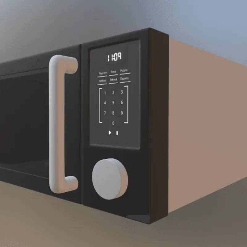 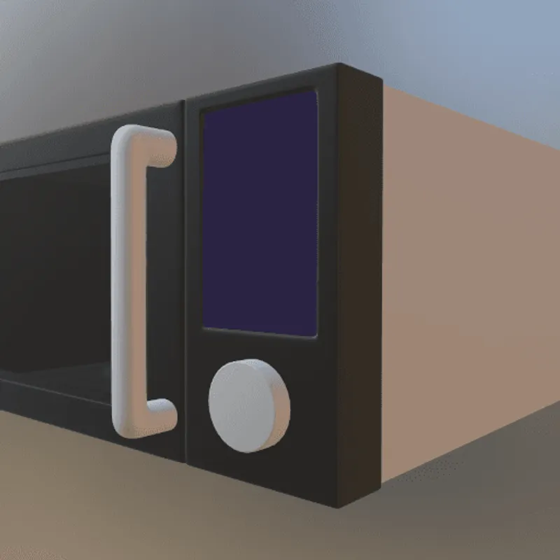 Inventor Notes: Basic texture mapping capabilities primarily for visualization and rendering purposes through material assignments and appearance properties. Impact: Texturing describes the process or refining the visual appearance of a 3D model's surface through additional 2D or 3D data, defined in a different reference system. The by far most common use of texturing are 2D texture images, applied to model visual material properties the 3D surface. Other cases include the use of procedural 2D or 3D funtions that produce intensity or color signals, which are then mapped to the 3D surface. For the vast majority of these cases (all of them except for 3D procedural functions), a parameterization or "Texture Mapping" is needed, which maps the 2D content to the 3D surface. Coming from a 2D coordinate space with coordinate axes often entitled U and V (in contrast to XYZ, which are the 3D surface positions), this process of mapping is also called UV Mapping, and it can be done with a dedicated UV map, or through a live mapping (e.g., box mapping). In this example, a texture image is applied to the 3D model to give the control panel a realistic look. Without support for texturing, the panel would have to use a single material instead, or all controls (including text) would need to be modeled through 3D geometry, instead of a 2D texture image. |
| Texture Transforms | Texture Transforms Support: Navisworks: Full support | Inventor: Partial support 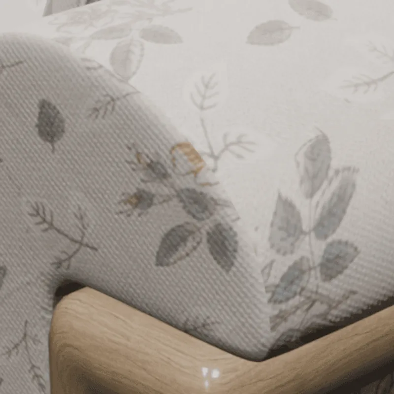 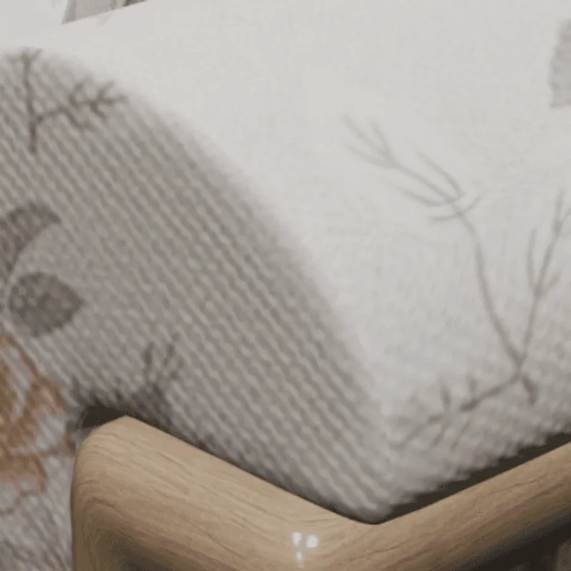 Inventor Notes: Limited texture transformation support mainly through material properties and visual styles for presentation purposes. Impact: Texture transforms describe transformation operations that are applied to 2D texture images or UV coordinates when using 2D texture data on a 3D surface. They can be used, for example, to make sure that material patterns are using real-world scale when rendered on the 3D surface. In this example, such a pattern is used and scaled with the help of a texture transform. Without support for this feature, the texture pattern shows up at the wrong scale. |
| Texture Compression | Texture Compression Support: Navisworks: Full support | Inventor: No support   Impact: Texture compression refers to a process of compressing 2D texture images for memory-efficient rendering (and sometimes for efficient transmission). The decompression of compressed texture data is therefore performed on-the-fly during rendering, so that it never has to be stored in unpacked form, but can be kept as-is in GPU memory. Formats supporting texture compression methods, such as the ones offered by glTF through KTX2 containers, therefore allow 3D models to use a smaller memory footprint on the client device during rendering. This can speed up rendering time, and also make it possible to store and use larger amounts of texture data than it would otherwise be possible. |
| Multiple UV Channels | Multiple UV Channels Support: Navisworks: Full support | Inventor: Partial support 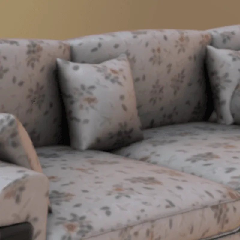  Inventor Notes: Basic UV mapping support through material assignments, focused on mechanical visualization rather than complex mapping workflows. Impact: Multiple UV channels allow the optimized and sophisticated use of various 3D modeling features at once. For example, one can use one set of UVs and 2D texture data to model a tiling texture or procedural material, and another UV set to leverage a global lightmap or occlusion map of the 3D model. In this example, a combination of tiled texture (UV channel 1) and baked ambient occlusion map (UV channel 2) is used. Without support for this feature, one needs to either give up the tiling property (e.g., by using a tool like RapidPipline to bake a single texture atlas), or give up the ambient occlusion map, as only one UV channel will be usable. |
| Procedural Textures | Procedural Textures Support: Navisworks: Partial support | Inventor: No support 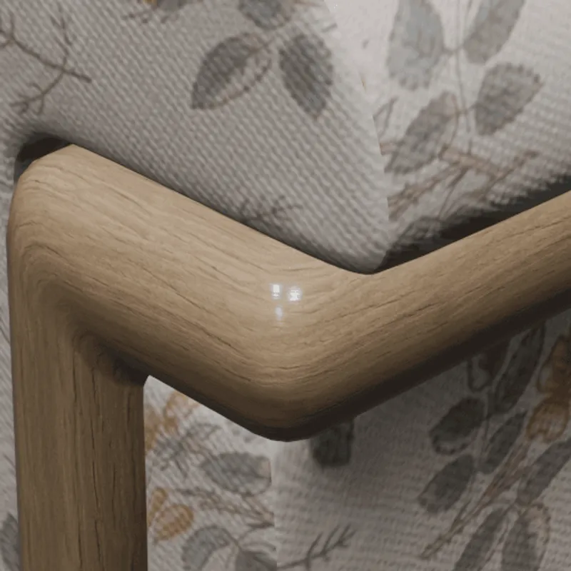 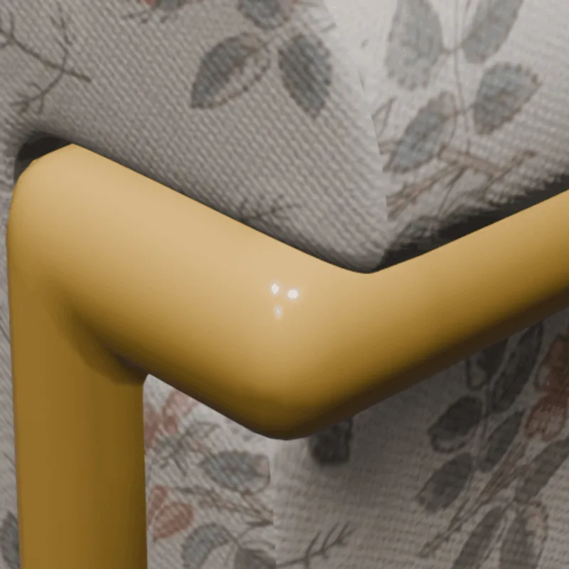 Navisworks Notes: Limited procedural texture support, mainly through imported materials from CAD systems rather than native procedural generation capabilities. Impact: Procedural texture allow the modeling of surface details through mathematical functions, along with artistic control over various parameters. Typically, they are used for patterns like wood grain or other semi-regular structures. Since they are not using any pixels as source data, procedural textures have, in principle, infinite resolution and are very lightweight to describe. In this example, a procedural texture is used to model the look of a wooden material. Without support for this feature, in this case, the wooden parts won't show any visible details. |
| Embedded Textures | Embedded Textures Support: Navisworks: Full support | Inventor: Partial support   Inventor Notes: Textures can be included with material definitions but with limited embedding capabilities compared to graphics-focused formats. Impact: Embedded textures allow the storage and exchange of an entire 3D model and its materials within a single file, by embedding the texture images directly into the 3D file (and not storing them as separate image files). Without support for this feature, textures have to be stored in separate image files, and referenced from the main 3D model file. |
| Normal Mapping | Normal Mapping Support: Navisworks: Full support | Inventor: No support 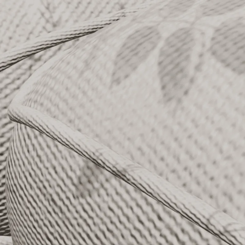 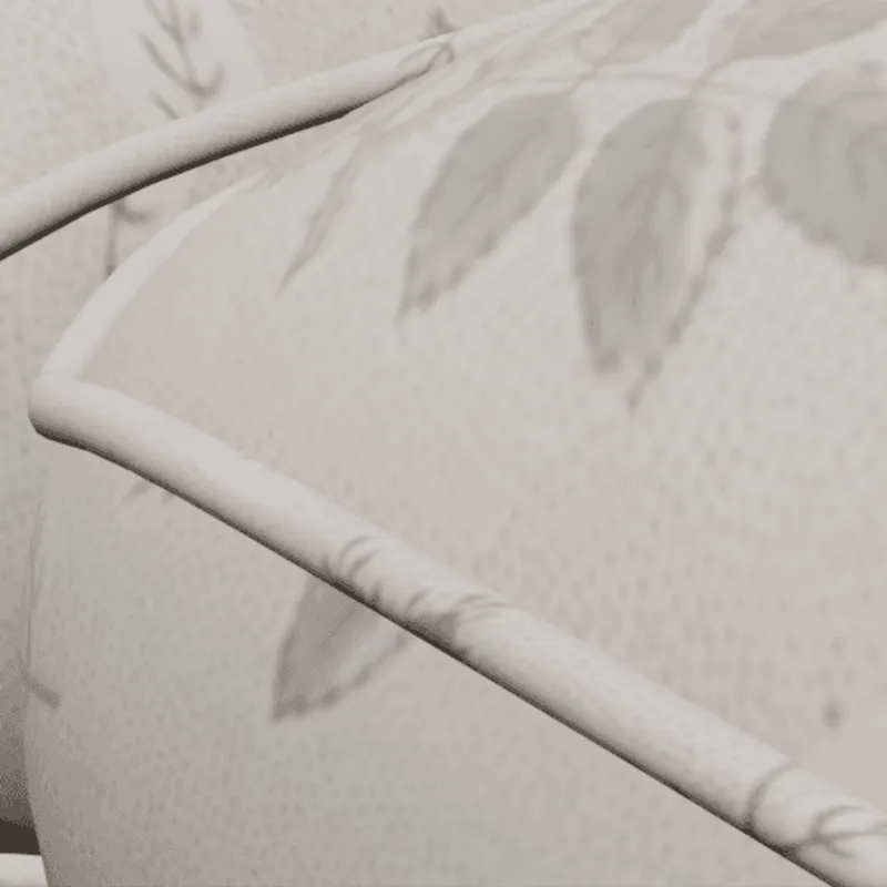 Impact: Normal maps are used to model shading differences that are arising from small geometric details on a surface, such as fabric structures, visible gaps between bricks forming a wall, or rough rock surfaces. In this example, a normal map is used to model a fabric structure. Without support for this feature, the rendered fabric will look smoother than it actually is in the real world, as the fabric structure won't be visible. |
| PBR Materials | PBR Materials Support: Navisworks: Full support | Inventor: Partial support  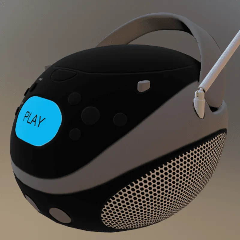 Inventor Notes: Basic physically-based rendering material support through appearance properties for realistic visualization and presentation. Impact: PBR materials enable Physically-Based-Rendering (PBR) for a standardized, photorealistic look of rendered images. PBR uses concepts like metallic-roughness or specular-glossiness properties and a microfacet-based modeling of the surface, using a concept called BRDF (Bi-Directional Reflectance Distribution Function). In this example, PBR materials are used to achieve realistic looking plastic and metal materials. Without support for PBR materials, only basic colors and shading can be used (for example, based on more simple shading models, such as the Blinn/Phong model). |
| Vertex Colors | Vertex Colors Support: Navisworks: Full support | Inventor: Partial support 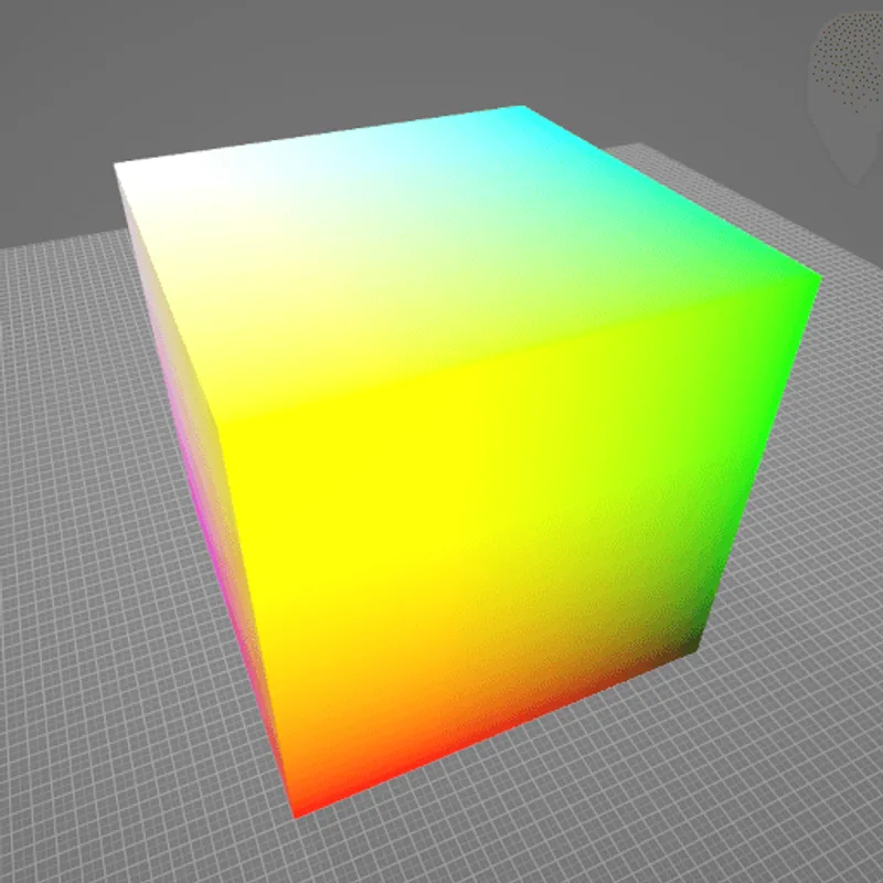 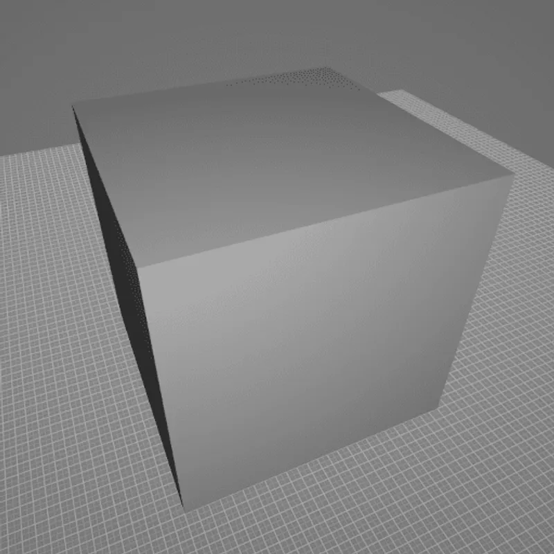 Inventor Notes: Limited per-vertex color support, primarily through part coloring and display properties rather than detailed vertex color manipulation. Impact: Vertex colors allow the attachment of colors to each vertex of a 3D model. This can be useful in scenarios such as scientific visualization, or when converting/meshing data from a colored 3D point cloud, for example. On the polygonal surface connecting the vertices, the respective vertex colors are usually smoothly interpolated. In this example, different colors are attached to the different corners of a cube. Without support for this feature, the cube won't have any colors. |
| Animations | Animations Support: Navisworks: Full support | Inventor: Partial support 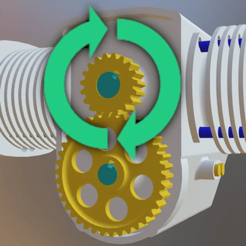 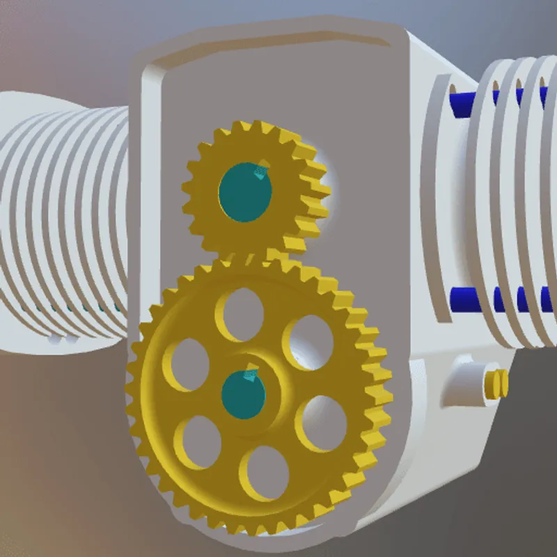 Inventor Notes: Basic animation capabilities for assembly motion studies, presentations, and design validation rather than complex character or organic animations. Impact: Animations are an important part of many interactive 3D assets, for example in real-time rendering (including games, XR training, assembly instructions, product demos, and other use cases). There are various kinds of animations that can be used on 3D models. In this example model, a rigid animation is used to make the gears spin. Without support for this feature, in this example, the gears won't move. |
| Rigid Animations | Rigid Animations Support: Navisworks: Full support | Inventor: Partial support 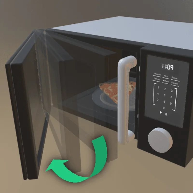 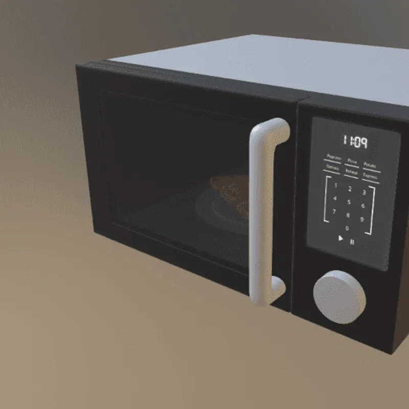 Inventor Notes: Supports rigid body animations for mechanical assemblies, motion studies, and presentation purposes to demonstrate product functionality. Impact: Rigid Animations are typically used to animate mechanical parts. In this example, the door of this 3D model of a microwave can be interactively opened or closed, using a rigid animation that gradually changes the 3D transformation of the door. Without support for this feature, in this example, the door will just stay in place and won't move. |
What's the best way to get Navisworks files into my 3D applications, and are there alternatives to using Inventor?
Doing 3D conversion right, especially at scale, can be tricky, as 3D data is in general a rather complex (yet very powerful!) medium. This also applies to Navisworks and Inventor files - the conversion guide above provides a rough first idea about that. Once you know what you would like to do, tools like RapidPipeline can help you perform the necessary steps, and to even automate the process for thousands or even millions of files.
Especially when introducing pipelines and workflows at scale in an enterprise context, it is usually good to rely on dedicated tools and expertise, making sure you do not introduce any steps into your 3D workflow that are detrimental to the final output's quality, or that take your team too much time (and money).
If you're interested to hire dedicated expertise from the best in the field to help your company reach your goals fast and reliably, please do not hestitate to contact DGG. Being the creators of RapidPipeline, and ambassadors for open 3D standards for more than a decade, we have been building some of the world's most advanced 3D pipelines, having processed many millions of 3D assets.
Therefore, our expertise will help you to reach your goals faster, at scale, and with the least possible friction, since we are focused on maximum interoperability.
To get started with 3D data conversion and optimization today, sign up for a free account!
If you have any questions, feel free to chat with our human team.
Best-in-Class 3D Processing in Your Favorite Tools.
100% Local Processing via Desktop Software.
Meet the Author

3D Knowledge Team
3D Technical Artists
RapidPipeline lets you convert, optimize and prepare your 3D models, easily. Try it today, or meet our human 3D experts. The Best-in-Class Tools for Your 3D Processing Jobs